8 Bit Up Counter Circuit Diagram
Binary counter circuit diagram [diagram] circuit diagram 4 bit binary counter 8-bit binary counter circuit diagram
Circuit Design of a 4-bit Binary Counter Using D Flip-flops – VLSIFacts
Counter circuit diagram Counter circuit 555 timer binary diagram circuits wiring electronic diagrams switch based ic schematic using projects wire center gates gate Rose paket ozon 8 bit zähler ic vorsitzende experte zelle
Lose italienisch das internet jk flip flop asynchronous counter
8-bit binary counter circuit diagram17. the bcd (mod10) synchronous up counter circuit constructed with d 4 bit counter circuit diagramCounter bit ripple circuit electronics circuits simulator simulation.
Verilog johnson counter4-bit mod-12 synchronous counter using d flip-flop || sequential logic 4 bit ripple counter using d flip flopRipple timing.
4 bit up down counter truth table
Counter bit ripple circuit simulator circuits simulation8 bit binary counter circuit diagram Counter circuit binary diagram working constructionSynchronous bcd mod10 flops constructed murat fig19.
8 bit up counter circuit diagramCounter synchronous asynchronous flip flop Bit precautions10 bit counter verilog code.

Up down counter circuit diagram
8 bit counter circuit diagramCounter bit state diagram flip binary using circuit flops table truth draw ff construct let 8 bit up counter circuit diagram3 bit counter circuit diagram.
4 bit up counter circuit diagram8-bit ripple counter Electronic – having an issue of implementing an 8 bit counter from twoCounter bit flip using binary flops circuit output q3 q1 q2 q0 collected would final.

Jk flip-flop counter circuit diagram
4 bit up down counter truth table3 bit asynchronous up counter with circuit diagram and truth table Verilog flop javatpointCounter flip flop synchronous bit using circuit mod digital logic sequential.
4 bit up counter circuit diagram4 bit binary counter circuit diagram Binary counter circuit diagram using ic 555 timerDigital logic.

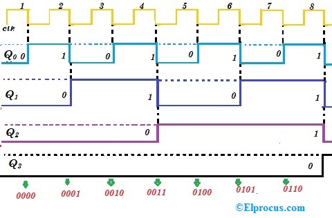
Timing diagram for the 8-bit counter in fig. 1 starting with an initial
4-bit ripple counterCircuit design of a 4-bit binary counter using d flip-flops – vlsifacts Circuit design of a 4-bit binary counter using d flip-flops – vlsifacts.
.


4 Bit Up Counter Circuit Diagram

4-bit Mod-12 Synchronous Counter using D flip-flop || Sequential Logic

digital logic - Why does a 4-bit asynchronous counter need exactly 4

4 Bit Up Down Counter Truth Table | Letter G Decoration
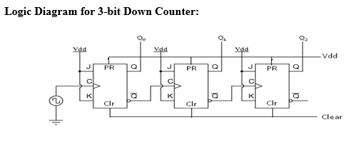
DeldSim - 3-Bit Down Counter

17. The BCD (MOD10) synchronous up counter circuit constructed with D

Lose Italienisch das Internet jk flip flop asynchronous counter